How to Use a Breadboard
The breadboard is a very convenient tool for assembling circuits. But you need to spend some time to figure out how it works and “get your hand in”. We have prepared breadboard operating instruction, as well as exercises for training. The instruction is designed primarily for our students and teachers as a methodological guide.
Breadboard layout
You can see there are quite a few units on the breadboard. We will connect wires to them. But we need to understand how it works. Let’s break one for this end (the budget of the article has grown by 2 dollars. ):
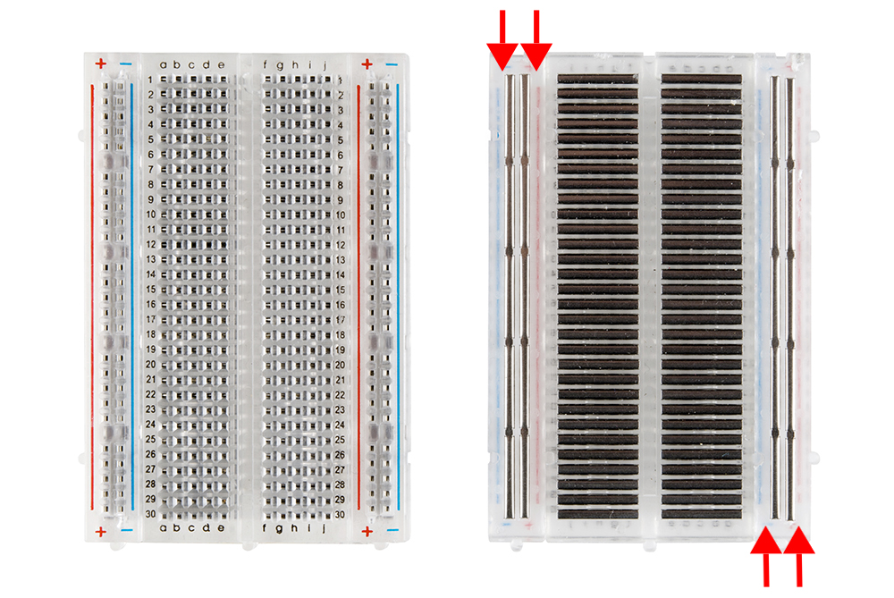
We have disassembled the breadboard and see that there are wires inside. Moreover, they are stacked in a certain order. The wires in the middle sit vertically, and the wires at the edges are horizontal.
Our units are also connected. The units in the middle are connected by series, and the units at the edges are connected by lines.
That is, if we insert two wires in one series, they will be connected to each other. It’s similar with the line. If we insert in one line (signed + and -), they will also be connected
This is the whole point of the breadboard. By inserting components into certain units, we will connect them to each other through wires that lie under them.
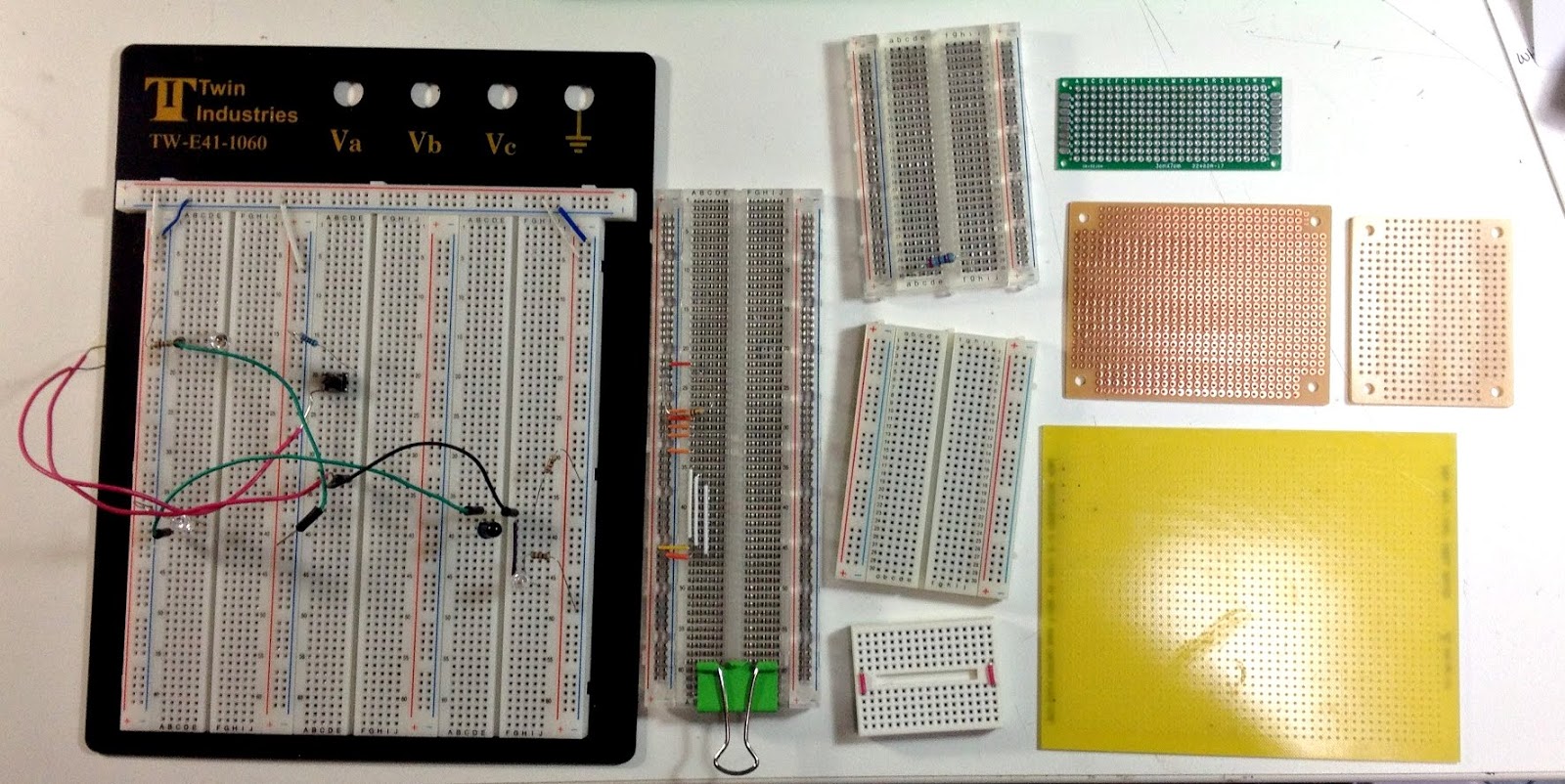
Photo 2. Breadboards come in different forms
Let’s assemble simple circuits on a breadboard
Let’s try to connect several components and make sure that everything works. To assemble these simple circuits, we will use the components:
| Name | Connection feature | Function | Picture |
| LED | this is a polar component, it has + and — (or anode and cathode) | Lights up beautifully | 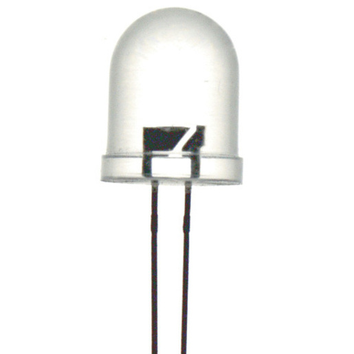 |
| Resistors | for our experience, we will need a resistor from 300 to 1000 ohms | Limits the current so that the LED does not burn out | 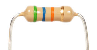 |
| Tact switch | With two or four contacts | Closes and opens the circuit | 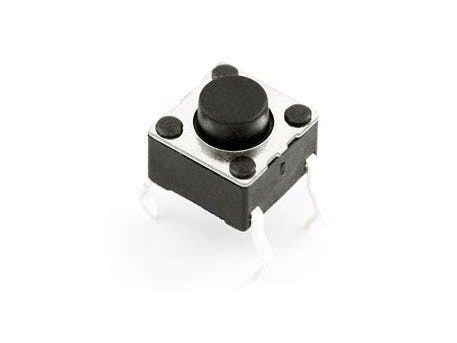 |
| Battery compartment | With two 1.5 volt AA finger batteries each | Powers the circuit |  |
| Arduino Nano Board | Inserted into the breadboard | Controller that allows us to program electronic circuits | 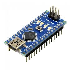 |
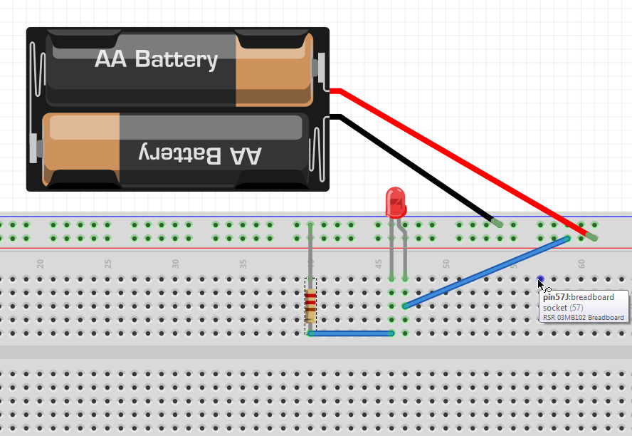
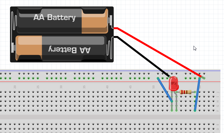
Exercise 1. Make the LED light up.
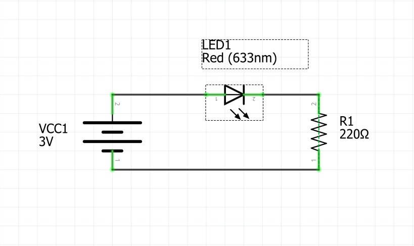
The meaning of the diagram is as follows: an electric current passes through the LED and it lights up, while the resistor limits the current so that the LED does not burn out.
Our version of the assembly on the breadboard.
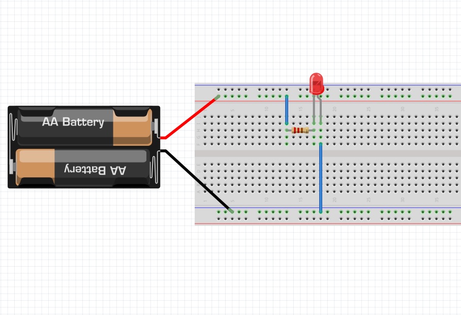
Please note that it is convenient to connect power to horizontal series, make common + and — out of them. These signs on some breadboards are just a hint for easy connection. Actually, it is often easy to have a common “bus”, a common wire with a plus and a minus. But that doesn’t mean you can’t connect something else in there.
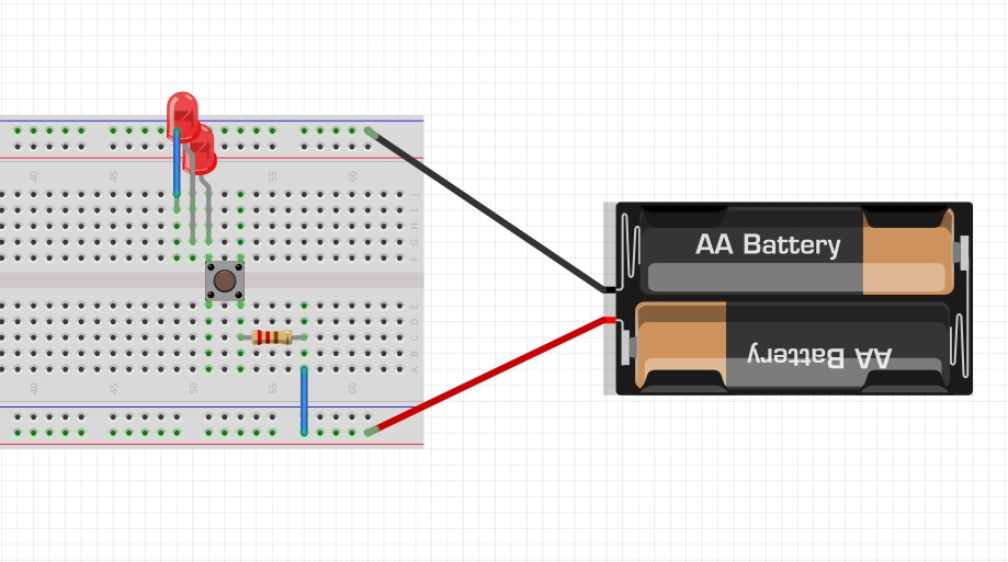
Exercise 2. A circuit with two LEDs connected in sequence and a switch.
Let’s complicate our circuit a little, now we will light two LEDs through the switch. The switch will allow us to close and open the circuit and thus control the switching-on of LEDs.
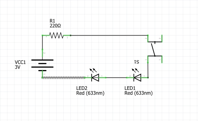
Try to assemble this circuit yourself. Below is our solution.
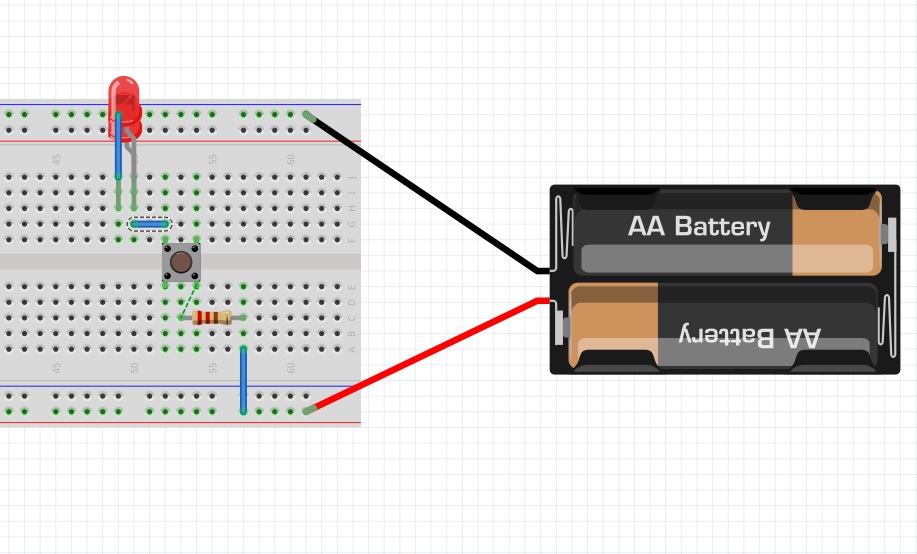
Exercise 3. Parallel connection of LEDs
We will assemble the following circuit with two LEDs connected in parallel. It’s worth mentioning that when connected in series, the plus of one component is connected to the minus of another, and when connected in parallel, the plus (or anode) of one component is connected to the plus of another, also with a minus (cathode).
4) Под4) Connecting a LED to an Arduino board.
In classes, we often use an Arduino board — our computer, with which we program electronic circuits and robots. Let’s figure out how a breadboard is used with an Arduino nano.
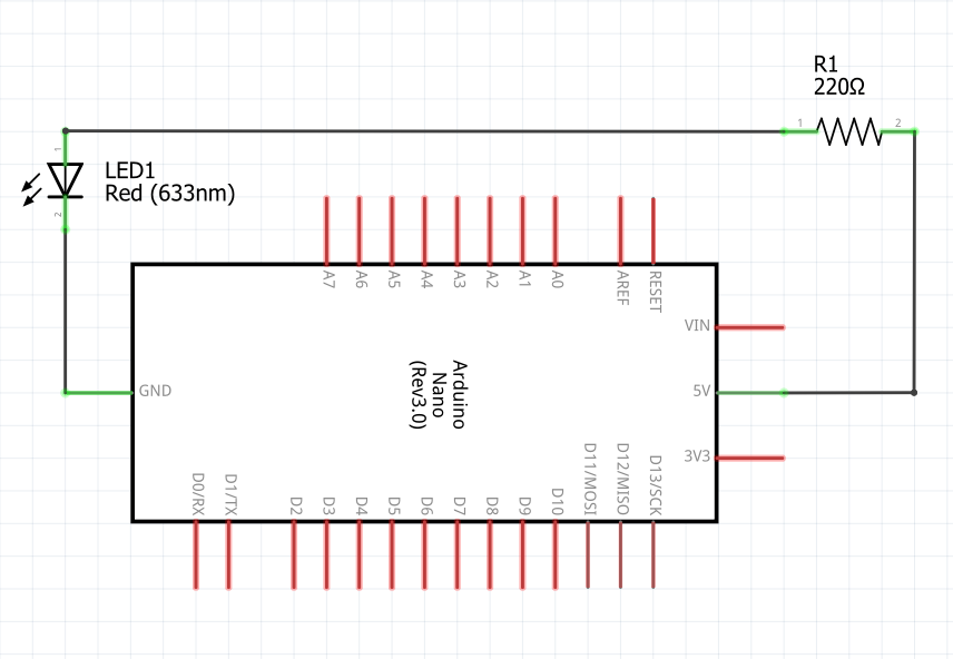
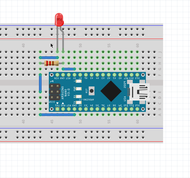
Let’s assemble a circuit like this. On it, the LED is powered by the output of the Arduino Nano 5V board (this port does not need to be programmed, it always provides constant 5 volts).
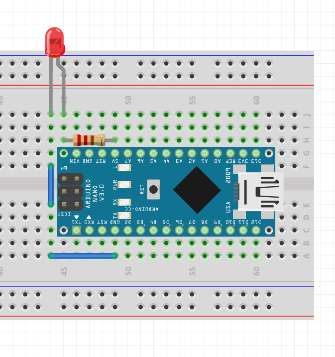
When assembling circuits on a breadboard with an Arduino board, be careful: when you extend the wires between the series, do not get into the series with the GND pin (Ground), otherwise a short circuit may occur. Try to keep in mind which stems on the board are working at the moment (voltage output or input), and which are not involved.
Short circuit
The main thing, when assembling circuits on a breadboard, is not to assemble a short circuit. What is a short circuit? It is when we connect the contacts of the circuit not as intended and a very large current passes through the circuit. We must always make sure to assemble the circuits on the breadboard in such a way that there is no short circuit.
In our breadboard operating instruction, we have prepared several schematic diagrams for you. Let’s practice determining the place of a short circuit.
Addition: Fritzing program, prototyping circuits
To create illustrations for the breadboard operating instruction, we used the program Fritzing http://fritzing.org/home/ . By using it, you can outline how the components will be placed on the breadboard, draw a schematic circuit diagram and even go from drawing diagrams to creating your own printed circuit board, which can be made with no help or ordered at the factory.
Although the program has not been updated for a long time and it does not have the most modern electronic components, it is quite convenient for beginners, we recommend it!